I was excited to try the new CH32V003 microcontroller from WCH out of China. It promises to be a cheap and versatile microcontroller that costs about 10¢ and can be easily flashed and integrated into a PCB project (I plan to use it for I2C logic control), and more impressive is that it's built on RISC-V architecture. So I bought a number of bare ICs, as well as this development board, and the chip must be flashed by the WCH's LinkE device.
Once the hardware was secured, I also had to install the dedicated MounRiver IDE, which can be hard to find but is available here. This is built on Eclipse, but includes some extra packages and interfaces specifically for WCH devices.
You can find a general programming datasheet for the CH32V003 here. For the rest of this post, we will be wiring and running the default MounRiver script, using the LinkE and Development Board.
Plug the LinkE's USB port into your computer. I used jumper cables to connect the following pins from the LinkE, to a breadboard which held the CH32V003 Development Board.
| LinkE Pin | DevBoard Pin |
|---|---|
| 3V3 | V+ |
| GND | GND |
| Tx | PD6 / Rx |
| Rx | PD5 / Tx |
I assume you've already installed MounRiver IDE and created a new project. The default project in MounRiver, found in User > main.c, is the following (my comments added for clarity):
#include "debug.h"
vu8 val; // Sample global variable, type vu8 = 'volatile uint8_t'

/*********************************************************************
	* @fn 	 	 	USARTx_CFG
	*
	* @brief 	 Initializes the USART2 & USART3 peripheral.
	*
	* @return 	none
	*/
void USARTx_CFG(void)
{
	GPIO_InitTypeDef 	GPIO_InitStructure = {0};
	USART_InitTypeDef USART_InitStructure = {0};

	// Enable the peripheral clock for GPIO port D and USART1
	RCC_APB2PeriphClockCmd(RCC_APB2Periph_GPIOD | RCC_APB2Periph_USART1, ENABLE);

	/* USART1 TX-->D.5 	 RX-->D.6 */
	GPIO_InitStructure.GPIO_Pin = GPIO_Pin_5;
	GPIO_InitStructure.GPIO_Speed = GPIO_Speed_30MHz;
	GPIO_InitStructure.GPIO_Mode = GPIO_Mode_AF_PP; // Sets the pin to 'Alternate Function Push-Pull mode' (necessary for UART TX)
	GPIO_Init(GPIOD, &GPIO_InitStructure); // Initialize GPIO pin 5 as Tx

	GPIO_InitStructure.GPIO_Pin = GPIO_Pin_6;
	GPIO_InitStructure.GPIO_Mode = GPIO_Mode_IN_FLOATING; // Floating to receive data
	GPIO_Init(GPIOD, &GPIO_InitStructure); // Initialize GPIO pin 6 as Rx

	USART_InitStructure.USART_BaudRate = 115200;
	USART_InitStructure.USART_WordLength = USART_WordLength_8b;
	USART_InitStructure.USART_StopBits = USART_StopBits_1;
	USART_InitStructure.USART_Parity = USART_Parity_No;
	USART_InitStructure.USART_HardwareFlowControl = USART_HardwareFlowControl_None;
	USART_InitStructure.USART_Mode = USART_Mode_Tx | USART_Mode_Rx; // Enable Tx and Rx

	USART_Init(USART1, &USART_InitStructure); // Initialize USART comm channel
	USART_Cmd(USART1, ENABLE); // Enable USART comm channel
}

/*********************************************************************
	* @fn  		main
	*
	* @brief 	 Main program.
	*
	* @return 	none
	*/
int main(void)
{
	NVIC_PriorityGroupConfig(NVIC_PriorityGroup_1); // Set NVIC priority (see NVIC in appendix below.)
	SystemCoreClockUpdate(); // This updates the `SystemCoreClock` variable to reflect the current CPU frequency. Needed for proper timing of peripherals.
	Delay_Init(); // Delays depend on system clock frequency. Init delays.

#if (SDI_PRINT == SDI_PR_OPEN)
	SDI_Printf_Enable(); // Print to Serial Debug Interface if available.
#else
	USART_Printf_Init(115200); // If no SDI, use UART for printing debug messages.
#endif
	printf("SystemClk:%d\r\n",SystemCoreClock);
	printf( "ChipID:%08x\r\n", DBGMCU_GetCHIPID() );

    USARTx_CFG(); // Run USART config function from above.

	while(1)
	{
		while(USART_GetFlagStatus(USART1, USART_FLAG_RXNE) == RESET) // Wait forever until the USART receives data and the FLAG_RXNE is set to RESET
	 	{
	 		/* waiting for receiving finish */
	 	}
	 	val = (USART_ReceiveData(USART1)); // Write received data to 'val'
	 	USART_SendData(USART1, ~val); // Send 'val' data over USART Tx
	 	while(USART_GetFlagStatus(USART1, USART_FLAG_TXE) == RESET) // Wait forever for Tx completion flag to RESET
	 	{
	 	 	/* waiting for sending finish */
	 	}
	 	// This loop will wait forever for incoming Rx data, then immediately send that data back over Tx, and go back to waiting.
	}
}
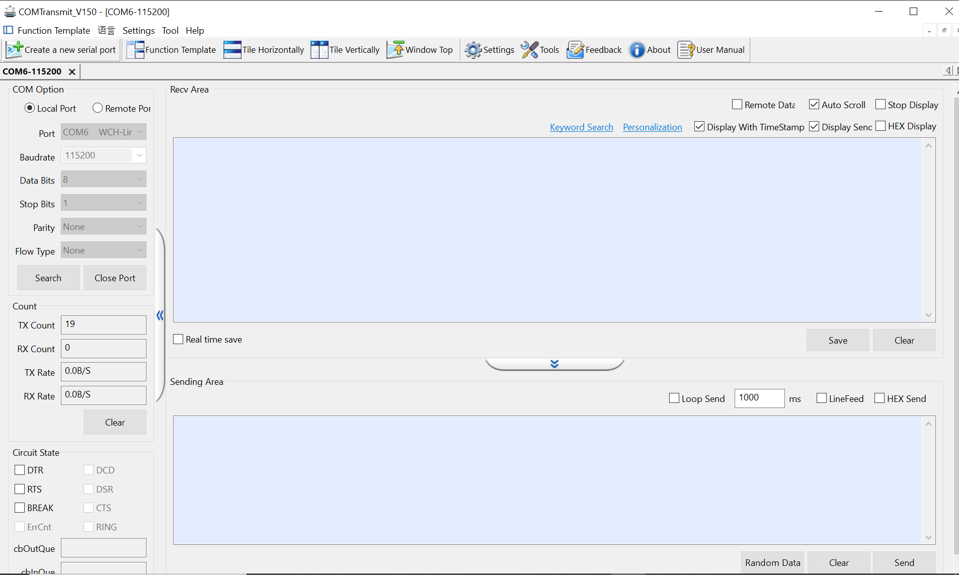
You can build this project by hitting CTRL + B, F7, or by clicking Project > Build Project. You can run it at Debug > Run. And most importantly for this script, you can click on Tools > Serial Port Debug Tool to open another window which will allow you to communicate with the chip. Set the "Port" to the one recognized as a WCH device, and the baud rate to your chosen baud rate (115200 in this example), and click "Open Port". If the script is running, then you'll be able to type into the bottom panel, hit "Send", and see it transmitted back into the top panel.